Realsoft Graphics Oy |
NURBS Surfaces
|
|
|---|---|---|
 |
Chapter 4. NURBS Curves and Surfaces | 
|
Realsoft Graphics Oy |
NURBS Surfaces
|
|
|---|---|---|
|
|
Chapter 4. NURBS Curves and Surfaces |
|
Many of the direct curve manipulation tools, such as Break and Sharpen, can also be applied to surfaces. The only difference is that surfaces have two parameter directions (called u and v) in which they can be manipulated.
|
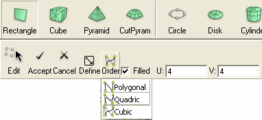
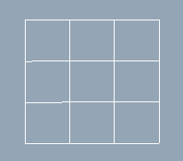
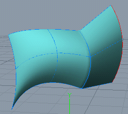
In this tutorial, we will demonstrate these direct NURBS mesh manipulation tools. The NURBS tab contains tools to create basic NURBS surfaces with freeform, circular and rectangular shapes. Let's create a rectangular cubic NURBS mesh, which consists of 4 x 4 control points: 1. Activate the NURBS/Rectangle tool. As always, the control bar shows you the tool specific options. |
 |
|
Set Order to cubic, make sure Filled is checked and specify the control point count 4x4 through the U and V fields. 2. Then enter two points through a view window to define a geometry for the rectangle. |
 |
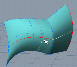
To switch to the curve editing mode:
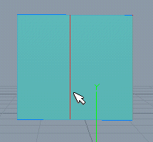
1. Select the mesh. As usual, the control bar shows you the tools, which can be applied to the selected mesh.

|
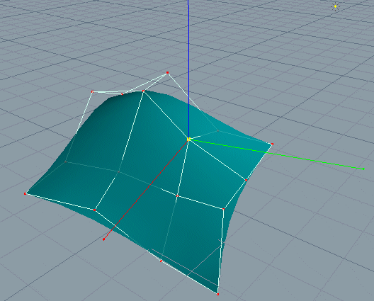
2. In the control bar, set the Edit control to Curves. Just click on the Edit icon and select Curve from the drop down menu. The mesh now shows you two vertical and two horizontal curve handles. When you move the mouse over a curve handle, the color of the curve is changed. As usual, you can move any curve simply by dragging it with the mouse. You can also multi select any number of curves and apply any transformation or deformation tool to them. |
 |
|
Just like you can add a new point to a curve, you can add a new curve to a mesh. 1. Use the NURBS/Rectangle tool to create a planar cubic NURBS mesh consisting of 4x4 control points. 2. Select the Add V Directed Curve pop-up menu item of the Add tool. Hint: you can also use the compass menu to activate the tool. |
 |
 |
|
|
Similarly, you can add a new horizontal curve to the mesh. Just select Add U Directed Curve from the pop-up menu of the Add tool and drag over the mesh to define the position for the curve. Most of the direct mesh manipulation tools work this way. |
 |
|
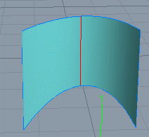
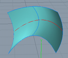
The Sharpen tool works similar to the Add tool. The only difference is that the inserted curve breaks the continuity of the mesh so that a sharp edge can be formed. Let's imagine we need to add a sharp V directed curve to the mesh we created above. 1. Select the Add V Directed Curve of the Sharpen tool and drag over the mesh to specify a position for the curve. The workflow is exactly the same as demonstrated in the previous example. The Sharpen tool doesn't change the shape of the mesh. However, the nature of the new inserted curve is revealed as soon as you modify the mesh. For example, move the rightmost vertical curve upwards a bit. |
 |
|
The Break tool breaks the mesh through the specified curve. Again, the workflow is similar to the previous Add and Sharpen tools. Let's split the mesh we created in the previous example into four parts: 1. Click the Break tool button. 2. Drag over the mesh to define the positions for the U- and V-directed curves. |
 |
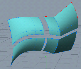 |
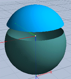
As you can see, two perpendicular curves passing through the specified point are rendered over the mesh. The reason for this is that clicking the Break button selects both U and V options. This is also true for Add and Sharpen tools. When a desired position for the curves is found, just release the mouse and the mesh is split into four parts by the curves. If the mesh is closed in the given direction, the specified curve just opens the mesh through the specified curve. Let's demonstrate this by applying the break tool to a NURBS sphere. The surface of a sphere is closed in its U direction but open in its V direction. |
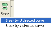 |
1. Switch to the top view and create a cubic NURBS sphere by using the NURBS/Sphere tool. 2. Switch to the front view and select Break by U Directed Curve pop-up menu item of the Break tool. |
|
3. Drag over the sphere to find a desired break curve. When found, release the mouse to accept the tool. Because the U directed curve forms a closed loop (the mesh is closed in its U direction), the tool split the surface into two separate parts. Correspondingly, the result is two separate NURBS meshes. |
 |
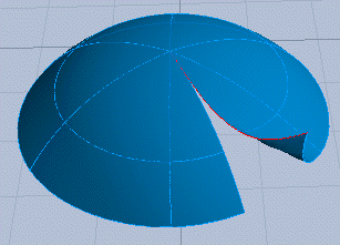 |
So, what happens if we break the mesh in its V direction? In that direction the surface is open: All V directed curves have end points at the poles of the sphere. 4. Select the north-pole mesh and activate Break by V Directed Curve. Then drag the mouse over the hemisphere to find a desired position for the break curve. When found, release the mouse. As you can see, new objects were not created. Also, the shape of the mesh remains exactly the same. However, the mesh was opened through the specified curve, as you can see by modifying the mesh. |
|
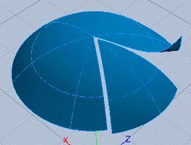
Now the semi sphere is open in the both parameter directions. Let's apply Break by V Directed Curve again. Now the result is two separate meshes. |
 |
Just like you can redefine the start point for a closed curve, you can redefine the start curve for a closed surface. Again, the only difference to the curve start tool is that now there are two parameter directions U and V in which the start curve can be defined.
|
NURBS meshes support a parameter called Weight. The weight parameter controls how strongly the control point in question affects the corresponding surface point (knot point). The higher the weight, the stronger the control point pulls the surface towards the control point. You can modify the weight parameter interactively as follows: 1. In Edit mode, select the desired control points. 2. Select the Weight tool and click the mouse in a view window. By moving the mouse up/down you can increase/decrease the weight of the selected control points. Click the mouse again to accept the tool. |
 |
![[Note]](../../gfx/note.gif) |
Note |
|---|---|
| You can also modify the weight of the selected control points by dragging them while holding down the Alt key. |
|
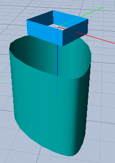
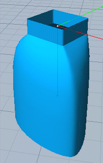
The Concatenate tool concatenates two meshes with each other provided that the meshes have an edge i.e. they are open at least in one parameter direction. The tool concatenates the two nearest edges. To use the concatenate tool, move the meshes to be concatenated so that the edges, which should be connected with each other, are placed side by side. The tool finds the nearest edges and connects them. |
|
|
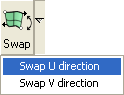
Sometimes you have to swap the direction of a mesh. For example, it may be necessary to invert the direction of a mesh to get it concatenated properly to another mesh. The Swap tool swaps the direction in both u- and v-directions. To swap the direction in one direction only, select the appropriate pop-up menu item from the tool button. |
 |
|
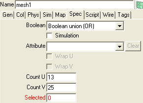
Let's imagine you have a mesh and you need to double the number of control points without changing the shape of the mesh. Editing the resolution attributes in the property window/spec tab does this. For example, you can double the value of the Count V field.
|
 |
You can close an open mesh and open any closed mesh by clicking the Close tool. The tool opens the mesh from its start curve.
If you have a number of meshes and you want to make them all closed, select the Close pop-up menu item associated with the Close tool.
|
Note |
|---|---|
| You can also use the Break tool to open a closed mesh from an arbitrary position. |
The Invert tool allows you to change the mesh so that it will pass through its original control points. Just click the tool button to apply the tool.
For example: if you import a polygonal mesh and want to convert it to a smooth cubic mesh, inverting the converted mesh compensates for the shrinking effect of degree elevation by smoothing.
The arrow keys (Up, Down, Left, Right) can be used for changing handle selection (curves/control points) in the Edit mode. The left and right arrow keys can be used to move the current selection in the U parameter direction. Correspondingly, the up and down keys allow you to move the selection in the V direction. This is very handy when modifying complex meshes. For example, to expand the current selection in the U direction, hold down the Shift key and hit the left and/or right arrow keys to select more curves.
|
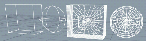
The To Nurbs tool converts geometric objects to NURBS form by approximating them with a set of NURBS meshes. For example, to convert an analytic cube and sphere to meshes: 1. Multi select the cube and the sphere. |
|
2. Activate the To Nurbs tool from the NURBS tool tab. 3. Specify the approximation density values Density U and Density V in the tool control bar. The default values U=1, V=1 define the minimum density. Set U=2, V=2. These values are sufficient for most cases. Click Accept to finish the conversion. |
 |
|
|
 |
|
| NURBS Curves |  |
Rotational Surfaces |